Updated July 22, 2021
Welcome to the Hagerty Radio Company web-site.
I would like to show you my work on direct-digital VFOs (variable-frequency oscillators). A direct-digital synthesizer (DDS) utilizes a high-speed, computational integrated circuit to generate precise, stable radio signals.
I have a versatile, high-performance VFO design that is available in an easy-to-build kit. Also available are several options and accessories, like a buffer amplifier for driving mixers and vintage tube transmitters. The kit for this amplifier can be built in an hour.
On the web-site you can read my QEX article on the VFO design, as well as the CQ article on my buffer amplifier. Also on the site are spectral plots, noise measurements, and reviews of my equipment. You can read on for additional circuit accessories and recent improvements.
Feel free to contact me with any questions, and I look forward to meeting your requirements. 73, Jim Hagerty WA1FFL
Show less
New! Rotary-Switched Overtone Display Software For Valiant 1 & 2
*For this option, please add $30.00 to the kit price.
WA1FFL's talk at the Boxboro Convention, 8/25/2012
VFO Driver Amp Article (published in CQ, June 2011)
 encoders.")
New- pc board for control switches and encoder.
All other parts included with kit. Fits BOTH detente and non-detente (Bournes EM14) encoders
An Attractive
and Functional Enclosure (Rotary Switched Version)
built by Ken Miller, K6CTW
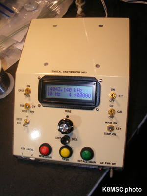
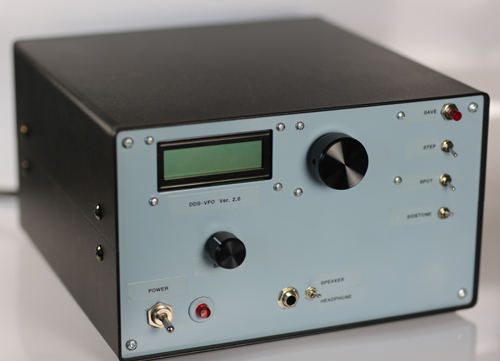
Here is a beautiful enclosure
for the VFO built by Dennis B. Adamson, K8MSC, which includes all switches and functionality | 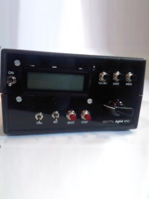
Another beauty built by Tom Noel, KC8JW |
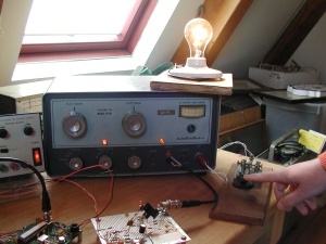
Jim's Direct-Digital 'Boat-Anchor!'
See the June 2011
issue of CQ.
|
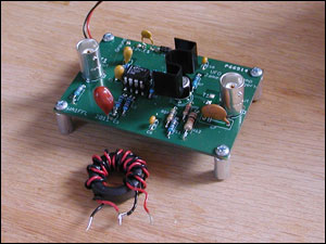 Here is the VFO buffer amplifier kit assembled, showing the output transformer winding detail.
Easily meets the drive requirements for the Hallicrafters HT-40, E.F. Johnson (Adventurer, Challenger and Viking 1 & 2), Heathkit DX-40, Millen 90800,
Here is the VFO buffer amplifier kit assembled, showing the output transformer winding detail.
Easily meets the drive requirements for the Hallicrafters HT-40, E.F. Johnson (Adventurer, Challenger and Viking 1 & 2), Heathkit DX-40, Millen 90800,
and many others. |
My current
project is a Direct-Digital VFO (variable-frequency oscillator)
using the Analog Devices AD9951.
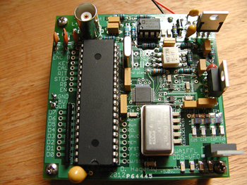
Updated VFO Circuit Board, Showing Ultra-Tough LT1086 Linear Regulators.
Driver Amplifier Kit for Tubes
I now have pc boards for the June 2011 CQ article, as well as a parts kit with instructions for the amplifier kit to drive vintage tube rigs. Price is $44.00 plus $5.50 shipping Click Here to Order
Complete VFO kits with displays
available for $160.00 plus $15.00 shipping
*** Ordering
information for the VFO Parts Kit is described
here.
Click
for New Spectral Plots 10
kHz Resolution 1 kHz Resolution
This circuit,
as well as an accompanying article is published in QEX
for May/June 2008. (1.4mb PDF)
Reprinted with the permission of the ARRL. Copyright ARRL.
The VFO features include:
- Full Coverage of 100 kHz
through 30 MHz.
- Improved Spectral Purity
Over Past Designs.
- Flash EEPROM Memory Storage
of 16 Frequency Configurations (Expandable to 32).
- RIT (Receive Incremental
Tuning), +/- 10 kHz in 10 Hz Steps.
- CAL Routine (1 Hz step increment/decrement
of carrier) to Compensate for Clock Oscillator Error.
- Transmit Offset {Selectable:
plus or minus CW (700 Hz) or SSB (1.5 kHz)}; can be tied
to the keying line or enabled separately.
- Frequency Tuning Steps of
1 Hz, 10 Hz, 100 Hz, 1 kHz, 10 kHz, 100 kHz, and 1 MHz, selectable
by rotating the tuning encoder while holding down the “step”
switch.
The
accompanying photos will give you an idea of what the VFO board
looks like all ready to go. As design updates are completed, important
applications information will be available on this site. I now
have a revised parts list, as well as several new filter designs
to choose from for the pre-filter (between the DDS output and the
input to the amplifier stage).
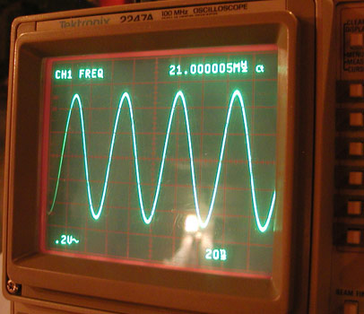
Clean Output Waveform at 21 MHz
|
|
|