Thank
you for visiting my amateur radio website. My name is James
Hagerty and I have been licensed since 1965. I am an electrical
engineer with 35 years’ experience. Updated April 1, 2011
See you at Dayton 2011, Booth #351
Jim's Direct-Digital 'Boat-Anchor!' See the June 2011
issue of CQ,
or visit us at Dayton Booth #351 (May 20-22) for details.
My current
project is a Direct-Digital VFO (variable-frequency oscillator)
using the Analog Devices AD9951.
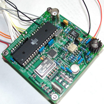
Circuit Board Close-Up.
Complete VFO kits with displays
available for $145.00 plus $5.00 shipping
*** Ordering
information for the VFO Parts Kit is described
here.
Click
for New Spectral Plots 10
kHz Resolution 1 kHz Resolution
This circuit,
as well as an accompanying article is published in QEX
for May/June 2008. (1.4mb PDF)
Reprinted with the permission of the ARRL. Copyright ARRL.
The VFO features include:
- Full Coverage of 100 kHz
through 30 MHz.
- Improved Spectral Purity
Over Past Designs.
- Flash EEPROM Memory Storage
of 16 Frequency Configurations (Expandable to 32).
- RIT (Receive Incremental
Tuning), +/- 10 kHz in 10 Hz Steps.
- CAL Routine (1 Hz step increment/decrement
of carrier) to Compensate for Clock Oscillator Error.
- Transmit Offset {Selectable:
plus or minus CW (700 Hz) or SSB (1.5 kHz)}; can be tied
to the keying line or enabled separately.
- Frequency Tuning Steps of
1 Hz, 10 Hz, 100 Hz, 1 kHz, 10 kHz, 100 kHz, and 1 MHz, selectable
by rotating the tuning encoder while holding down the “step”
switch.
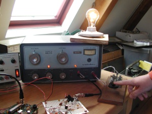
The
accompanying photos will give you an idea of what the VFO board
looks like all ready to go. As design updates are completed, important
applications information will be available on this site. I now
have a revised parts list, as well as several new filter designs
to choose from for the pre-filter (between the DDS output and the
input to the amplifier stage).
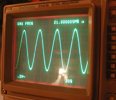
Clean Output Waveform at 21 MHz
|
|
|